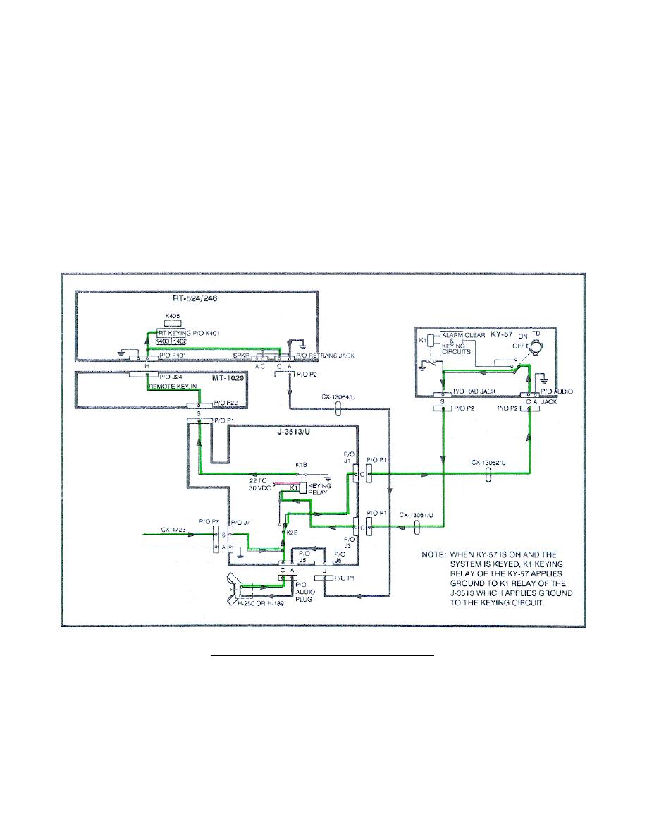
(2) The keying circuit from the CX-4723 pin S is applied to the J-
3513/U J7 pin S to J5 pin C (audio connector) (Figure 62) and through K2B to
J1 pin C, through the CX-13062/U to the KY-57 (KY-57 is turned OFF) Audio
jack pin C. Then out the KY-57 RAD jack pin S, through the CX-13061/U to J3
pin C of the J-3513, to the K1 keying relay.
(3) When the system is keyed (at a crew member's C-2298 or the J-3513
audio connector), a ground circuit (pin A) is completed through the handset.
When the PTT switch is pressed, 22 to 30 volts DC is applied and energizes
K1.
K1B closes, applying ground to the remote keying circuit, keying the
RT. (Trace these circuits on your system diagram.)
NOTE:
When KY-57 is ON and the system is keyed, K1 keying relay of the KY-
57 applies ground to K1 relay of the J-3513 which applies a ground
to the RT keying circuit.
Figure 62.
A-RT keying circuit.
71


 Previous Page
