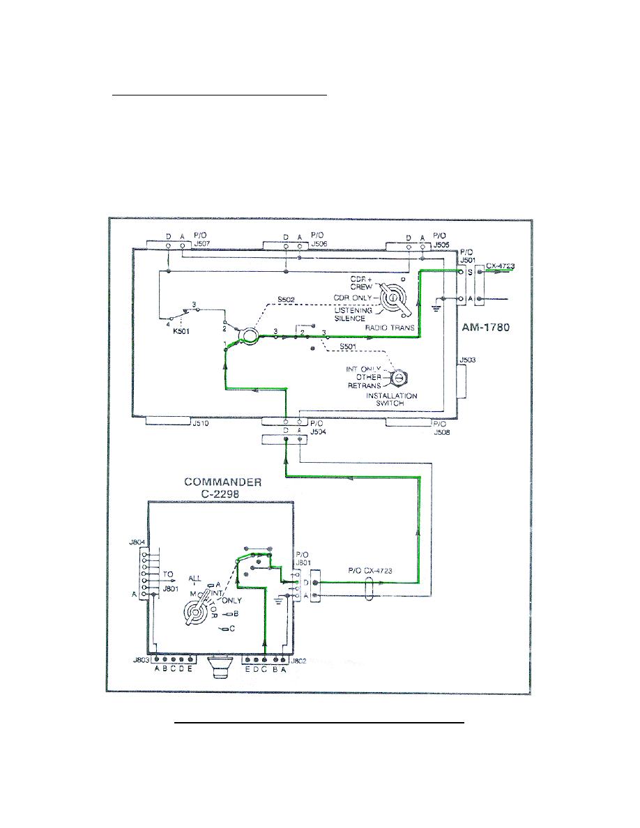
19. A-RT KEYING CIRCUIT.
a. Commander's A-RT keying circuit.
(1) The commander's keying circuit starts at the commander's C-2298
J802 pin C (Figure 61).
From pin C J802 the keying circuit is applied
through the MONITOR switch (when set to ALL, A, or B) to pin D of J801/J804,
through the CX-4723, to the AM-1780 J504 pin D. In the AM-1780 the circuit
is applied through pin 1 to pin 3 of switch S502 (set to CDR ONLY or CDR +
CREW) through switch S501 (when set at OTHER) to J501 pin S, and through the
CX-4723. (Trace this circuit on your system diagram.)
Figure 61.
Commander A-RT keying circuit.
70


 Previous Page
