1-36.
FUNCTION OF THE RF SECTION
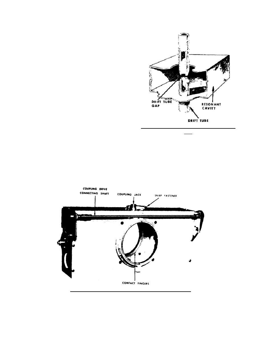
The RF section (fig 33) includes a DRIFT
TUBE, and from 2 to 6 RESONANT CAVITIES
placed at intervals along the tube. In addition to the
drift tube and resonant cavities, the RF section
usually includes a magnetic field coil assembly (not
shown). The combined action of the RF section's
components permits velocity modulation of the
electron beam. In turn, the velocity-modulated
electrons become density modulated and electron
bunches form that cause a large amount of
microwave power amplification for the output.
1-37.
THE DRIFT TUBE
The drift tube has a number of gaps (fig 33) at
intervals along its length. The number of gaps
equals the number of resonant cavities.
For
Figure 33. Resonant cavity surrounding drift tube
example, if there are three resonant cavities, there
gap.
will be three gaps. The resonant cavity surrounds
each gap and the ends of the drift tube sections
1-38.
THE RESONANT CAVITY
extend inside the cavity. Electrons flowing through
the drift tube cannot escape through the gaps into the
Resonant cavities are hollow chambers with
cavities because each gap is covered by a ceramic
conducting walls. They come in various sizes and
window seal. The ceramic window seal also
shapes (rectangular, circular, etc.) depending on the
maintains a vacuum inside the drift tube.
application. The kind of resonant cavity used in a
typical high-power klystron is as shown in figure 34.
Figure 34. Resonant cavity used in typical high power klystron.
344 L1
36


 Previous Page
