b. The resonant cavity is to the klystron
amplifier as the LC tuned circuit is to the
conventional electron tube amplifier. In fact, in the
replaces the LC tuned circuit as a frequency
determining device. The frequency determining
device for ultra-high frequencies (UHF) requires
extremely small values of capacitance and
inductance. This means that the resonant cavity has
capacitive and inductive properties.
c. You'll recall that when electrical energy
is applied to a capacitor, an electric field builds up
between its plates. Likewise, when electrical energy
is applied to a resonant cavity, an electric field
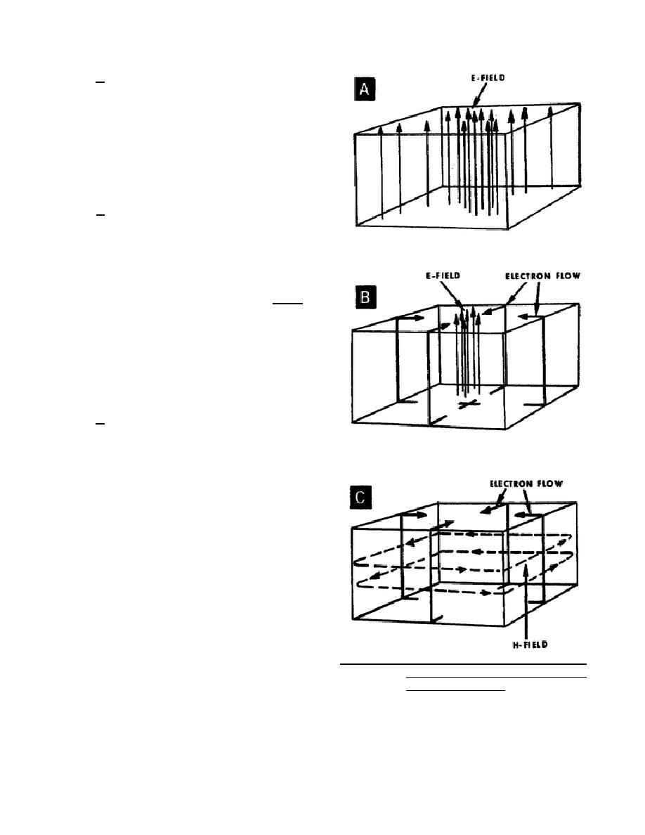
builds up between its inner walls. A representation
of the electric (E) field within a rectangular cavity is
shown in A of figure 35. The electric field exists
because a potential difference is developed within
the cavity between its upper wall and lower wall.
By use of appropriate measuring instruments, you
can determine the point of greatest potential
difference. As in A of figure 35, the point of
greatest potential difference between the upper and
lower walls is where the electric (E) field intensity is
greatest -- at the exact center between the upper and
lower walls.
d. When we charge a capacitor, it takes a
definite amount of time before the potential
difference (electric field) builds up to maximum
between the capacitor plates. The time required for
the electric field to reach maximum intensity is equal
to the time required for the electrons on one plate to
move to the other plate. A similar action occurs
within the resonant cavity when you apply electrical
energy between its inner walls. While the electric
(E) field is building up to maximum intensity
between two opposite walls, electrons flow between
the same walls. For example, let's consider the
actions of the electric (E) field and electron flow
within the cavity shown in B of figure 35. While the
electric (E) field is building up between the upper
and lower walls, electrons flow from the lower wall,
along the four vertical walls, to the upper wall.
Therefore, the upper wall becomes negative with
respect to the lower wall, because of the excess of
electron accumulation on the upper wall. In reality,
Figure 35. Resonant cavities' E-field (A), E-field
the paths of electron flow extend over the entire
and electron flow (B), and electron
surface
flow and H-field (C).
344 L1
37


 Previous Page
