(inside the cavity) is the capacitive element of the
resonant cavity. In addition, the center area between
the larger walls is where the electric (E) field
intensity and voltage potential difference are
greatest. The drift tube gap, therefore, is the point of
highest potential difference within the resonant
cavity.
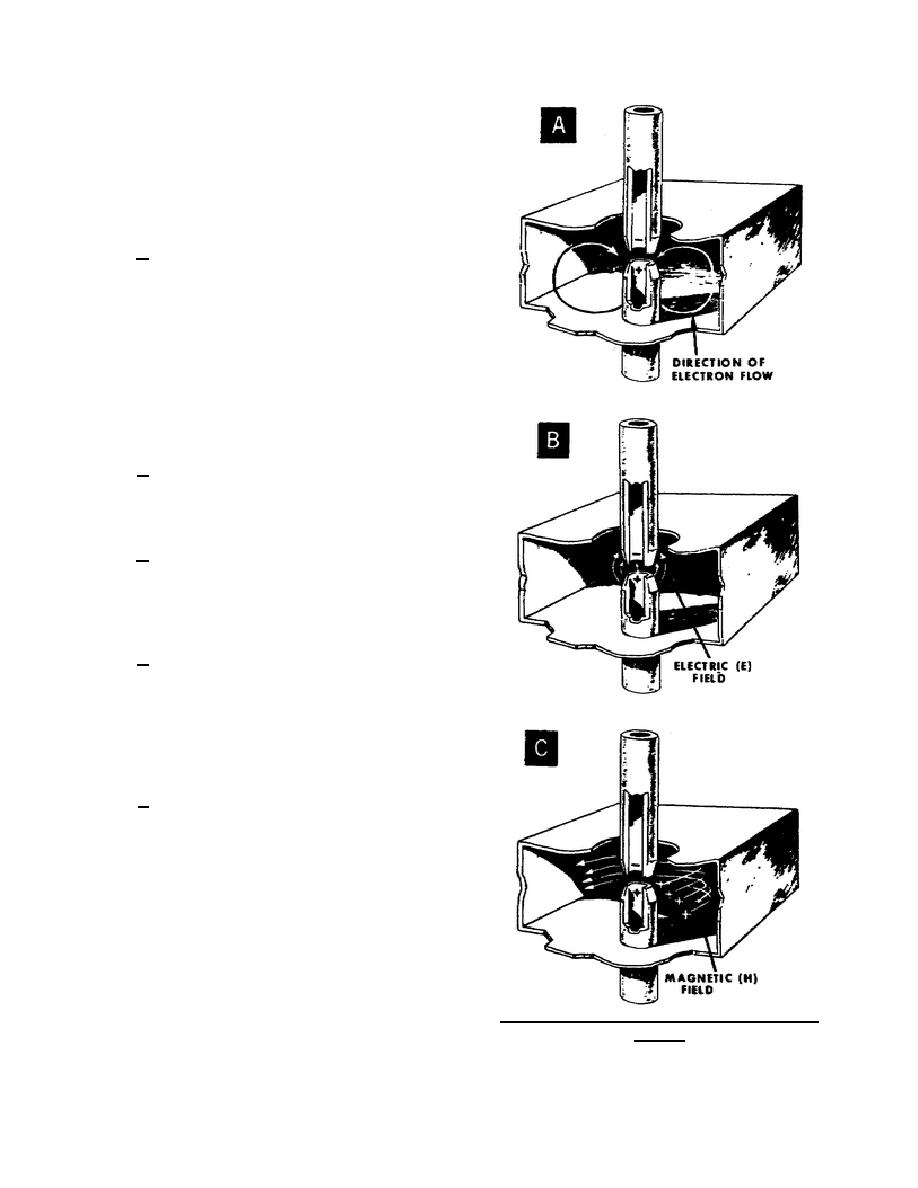
b. A potential occurs across the drift tube
gap when, and only when, the resonant cavity
oscillates. Because of the oscillations, electrons
flow from one tip of the drift tube to the other. An
example of the electron path during one-half cycle is
shown in A of figure 38. Remember that the
electrons make a sweeping path over the entire
surface of the cavity walls. The upper tip of the gap
becomes negative with respect to the lower tip
because of the accumulation of electrons on the
upper tip.
c. For the same half cycle, B of figure 38
represents the electric field extending from the
positive tip to the negative tip. The intensity of the
electric field is greatest between the drift tube tips.
d. Also for the same half cycle, C of figure
38 represents the magnetic (H) field. The intensity
of the magnetic field is greatest near the surface of
the walls because of the heavy current flow along
them.
e. The electric (E) and magnetic (H) fields
for one-half cycle are represented in A of figure 39.
On the next half cycle, the direction of current flow
reverses and the E and H fields also reverse as
shown in B of figure 39. So you can see that the E
and H fields periodically change in direction as well
as in intensity.
f. Because of the resonant cavity
characteristics, the electric and magnetic fields can
make these periodic changes or oscillations at the
rate of millions of times per second. However,
energy must be supplied to the resonant cavity in
order to keep the oscillations going. Otherwise, the
oscillations will eventually stop because of the small
amount of cavity resistance that dissipates energy.
The resonant cavity in the high power klystron can
use either of two kinds of energy sources (paras 9-11
below) for starting and sustaining oscillations.
Figure 38. Drift tube protrusion intensifies field
pattern.
344 L1
39


 Previous Page
