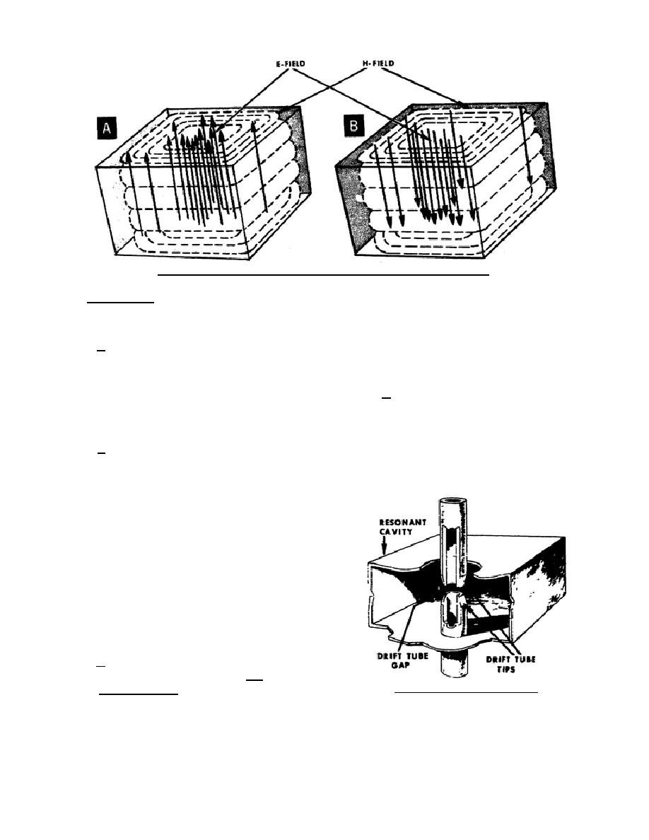
Figure 36. Electric and magnetic field pattern for alternate half-cycles.
of the low resistance conducting wall. The walls are
and the operating frequency being used with the
coated with a low resistance material to make them
cavity. The pattern shown in figure 36, however,
good conductors.
represents the most efficient mode. And to simplify
our discussion in this text, we will cover only one
e. Because the cavity's four vertical walls
operating mode -- the one represented in figure 36.
are actually conductors along which electrons flow,
a magnetic (H) field exists within the cavity. The
1-39.
CAVITY - DRIFT TUBE ASSEMBLY
electron flow generates the magnetic field. The
a. The drift tube sections extend through
magnetic (H) field loops are in a direction
the center of the larger walls of the resonant cavity
perpendicular to the direction of electron flow in the
as shown in figure 37. This narrows the center
vertical walls, as shown in C of figure 35.
spacing between the larger walls is equal to the
f. The electric and magnetic field
space or width of the drift tube gap. Thus, the drift
combination represents the presence of voltage
tube gap
potential difference and current flow within the
cavity. The voltage and current buildup and collapse
in the resonant cavity just like they do in the
ordinary LC circuit. Within the cavity, both the
voltage polarity and direction of current flow
alternate. The alternating voltage polarity causes an
alternating electric (E) field; the alternating current
flow causes an alternating magnetic (H) field. For
example, the diagram in A of figure 36 represents
the alternating electric (E) and magnetic (H) field
combination during one-half cycle. The diagram in
B of figure 36 represents the E and H field
combination during the next half cycle.
g. The electric (E) and magnetic (H) field
patterns as shown in figure 36 represent one of many
Figure 37. Drift tube sections.
possible operating modes of resonant cavities. The
operating mode for any particular resonant cavity
largely depends upon two factors: the cavity design
344 L1
38


 Previous Page
