h.
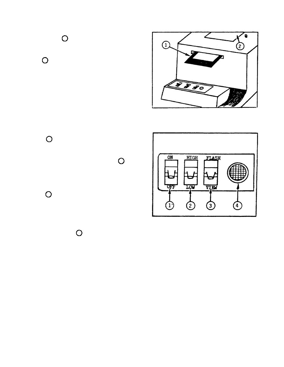
Filter Compartment and Holder
(fig 1-11).
1 - filter holder
slides in and out of the filter
compartment
easily,
allowing
insertion
of
filter
without
disturbing copy or opal view glass 2
.
The use of filters for color
correction will be dealt with later
in the course.
Figure 1-11.
Filter Compartment
and Holder.
i.
Control Panel (fig 1-12).
The
control
panel consists
of three
switches and a ready light.
ON-OFF
Switch 1 functions as a master
switch for the copier.
The view
light and electronic flash operate
only when this switch is in the ON
position.
HIGH-LOW Switch 2 -
controls power output of electronic
flash.
When in the HIGH position,
the unit will deliver four times
(two f/stops) the amount of light as
when in the LOW position.
FLASH-
VIEW Switch 3 in FLASH position,
the switch completes the circuit for
firing the electronic flash with the
camera shutter
release; in VIEW
position, the switch turns on the
view light
for illuminating
the
transparency, for focus and framing.
Figure 1-12. Control Panel
READY LIGHT LIGHT 4 - glows when the
FLASH-VIEW switch is in the FLASH position, indicating that the copier is ready
for operation - the view light is off and the electronic flash is ready to be
fired.
12


 Previous Page
