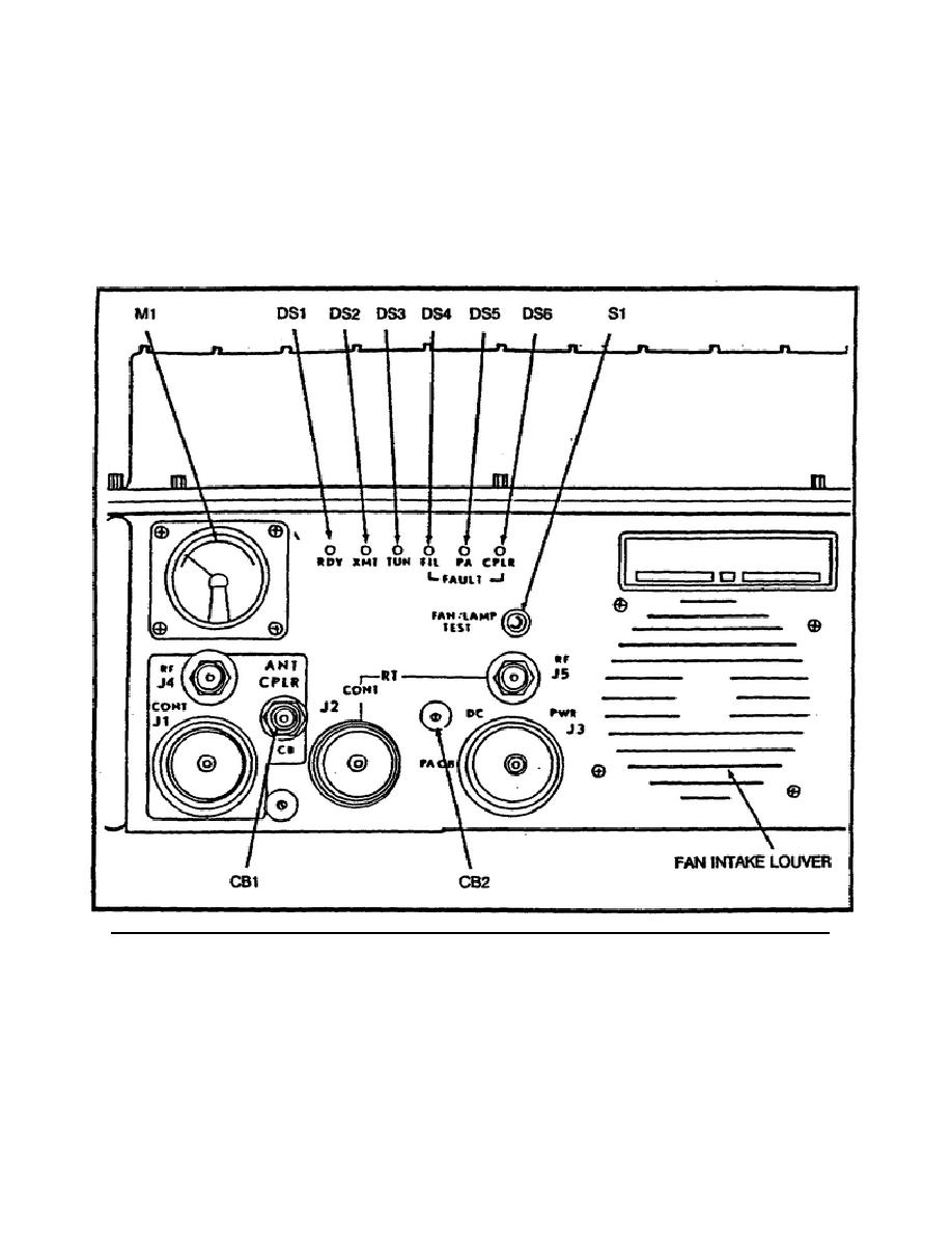
an audio indicator that power is present to the power amplifier and that the
indicators are all in working condition.
The 100-watt (w) to 400-watt switch
provides 100 w or 400 w of RF output power from the AM-6545 to the CU-2064 in
transmit. There are two RF jacks (J4 and J5) on the face of the power amplifier.
The J5 jack is connected to the AM-6879/URC. The J4 jack connects to the antenna
coupler. The J3 jack is a DC power input cable connection from the vehicle battery
or power supply.
The J2 jack provides power and control connections through the
AM-6879/URC to the RT-1209/URC.
The J1 jack provides power and control to the
antenna matching unit.
The M1 is a meter used for general support (GS)
troubleshooting and normally reads forward RF power.
Figure 6.
Operating controls and indicators, power amplifier AM-6545/GRC-193.
h. The fourth major item is the CU-2064/GRC-193A antenna coupler (Figure 7).
The J2 is the control connection from the AM-6545, and J1 is the RF to and from the
AM-6545 J4. The flag switch is a spring-loaded switch that normally leaves J4 open
for connection of a whip antenna while preventing seating of the 50-ohm antenna
base on J3. There are two wing nuts located on studs on the face of CU-2064 that
are marked GROUND. If this ground
6


 Previous Page
