3. INSTALLATION
KIT
INSTRUCTIONS
FOR
MK-2459/GRC-193A,
GENERAL-PURPOSE
INSTALLATIONS.
a. Use the base of the MT-6232 mount to locate and mark mounting hole
positions. This installation kit is for general use, and the location of the mount
must be determined by the required installation rather than a location being
specified.
b. Drill six 7/16-inch holes in the vehicle or shelf.
c. Place backing plates under the vehicle panel or shelf using 3/8-inch x l
1/2-inch bolts through the mount, shelf, and backing plate.
Add a flat washer,
lock washer, and nut.
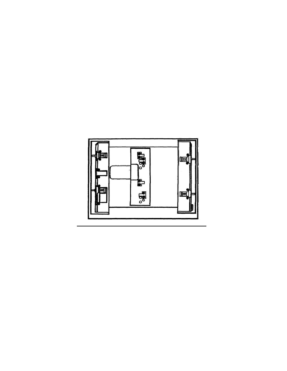
d. Adjust the wing-nut bars and cleats (Figure 9) on the top shelf so that
the cleats and wing-nut clamps match the notches in the sides of the AM-6545 and
CU-2064 for desired orientation based on the direction of the RF cable run. These
are held in place by large Phillips-head screws.
These cleats must be moved to
change orientation, and the wing-nut clamp bars must also be moved by removing the
Phillips-head, recessed screws that will be used to remount them.
Figure 9.
Cleat and wing nut clamp adjustment.
e. Cables designated W1, W2, W5, and W6 should be fed through the mount and
clamped with the clamps provided in the installation kit.
The clamps are screw
mounted into threaded holes provided in the mount frame.
Cable designated 34
should be attached to J6 of AM-6879 and lead around to the right side of the frame
as the AM-6879 is slid into the mount. Cables should be mounted inside the MT-6232
when it is received, but if they are not you must mount them. (See Figure 10.)
9


 Previous Page
