CAUTION
ALIGN COUPLER AND WHIP ANTENNA CABLE CONNECTOR BEFORE MATING AND FASTENING TO AVOID
CROSS THREADING.
IF THE COUPLER IS NOT PROPERLY GROUNDED TO THE FRAME, THE RADIO WILL NOT OPERATE IN
THE VEHICLE AND MAY DAMAGE EQUIPMENT.
i. The fans in AM-6545 are both sealed units that move air over heat
exchangers inside the bottom plate of the unit.
All connectors are located on
front panels except RT-1209/URC and AM-6879/URC.
The RT-1209/URC has a control
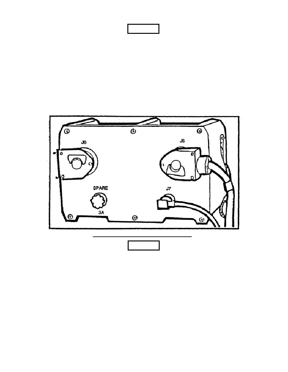
connector (AlJl) on the side. The AM-6879/URC has the JS, J6, and J? connectors on
the back with a spare fuse holder. J7 is a connector for RF cable to J5 of the AM-
6545. J5 of AM-6879 is the connector to control connector J2 of AM-6545, and J6 is
the connector to control cable to A1Jl of RT-1209 (see Figure 8).
Figure 8.
Rear view of AM-6879/URC.
CAUTION
BE SURE THAT COUPLER AND POWER AMPLIFIER AIR INLETS (FRONT OF UNIT) AND EXHAUST
PORTS (REAR OF UNIT) ARE NOT OBSTRUCTED BEFORE OPERATING EQUIPMENT.
8


 Previous Page
