Lesson 1/Learning Event 4
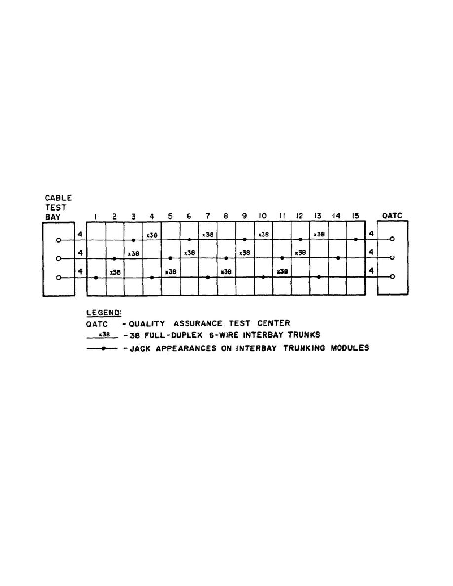
(b) Figure 1-8 is a trunking diagram of a typical interbay trunking
arrangement showing connections between 15 patching bays, the cable test bay
and the QATC bay. It provides 114 interbay trunks, 12 trunks between the VF
primary patch bay jackfield and a cable test bay, and 12 trunks between the
jackfield and the QATC bays. The trunks are arranged in three multiples of
five bays as follows:
Multiple 1:
Bays 1, 4, 7, 10, and 13.
Multiple 2:
Bays 2, 5, 8, 11, and 14.
Multiple 3:
Bays 3, 6, 9, 12, and 15.
Figure 1-8.
Typical Interbay Trunking Arrangement for
VF Primary Patch Bays
(c) Each multiple is served with 38 interbay trunks. The arrangement of
VF primary patch bays into multiples depends upon the circuit routing,
restoral, and patching patterns peculiar to each station.
14


 Previous Page
