Lesson 1/Learning Event 4
(b) The block and schematic diagrams of patching modules included the
designations for REC, SEND, DROP, LINE, EQUIP, and MON to correspond to the
jack appearances of circuits and leads on the module front panels.
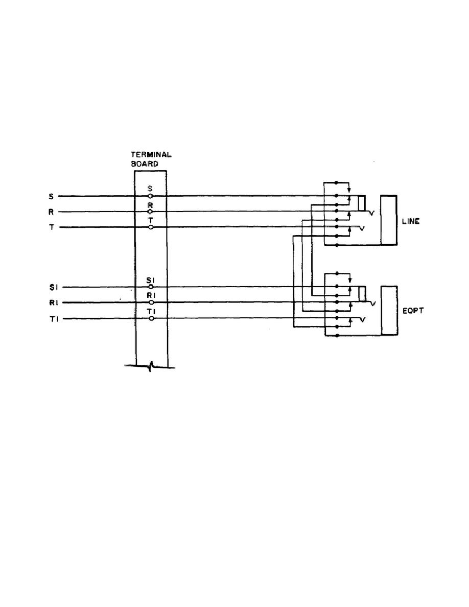
(c) According to the schematic
drawings, the tip and ring leads on the
line side are identified simply by
T and R, and on the equipment side as T1
and R1.
This facilitates lead
identification at the patching module
terminal boards, as shown in figure
1-6 below.
Figure 1-6.
Lead Designations for LINE-EQ Jack Set
(d) Figures 1-6 and 1-5 show monitor jacks on the line side only. This
is also reflected in the front panel layouts of figure 1-4, where each jack
set column contains only a single monitor jack. This arrangement, with the
monitor jack on the line side, is the minimum requirement stated by MIL-STD
188-310A. In some of the arrangements there is an additional monitor jack
on the equipment side to permit monitoring of the signal to the equipment.
12


 Previous Page
