Lesson 1/Learning Event 4
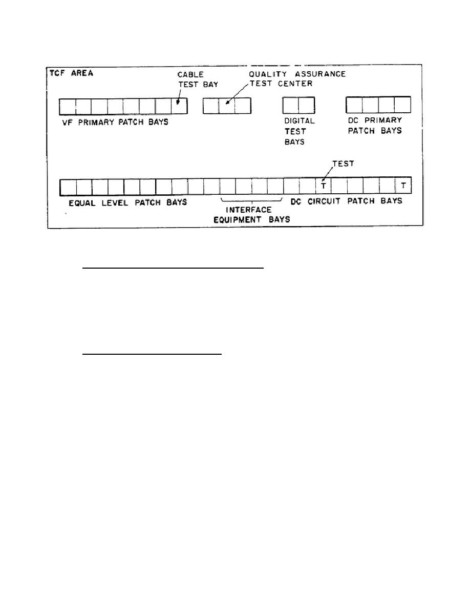
Figure 1-2.
Floor Plan Showing a Practical Arrangement of
Equipment Bays in a TCF
a. Voice-Frequency Primary Patch Bay.
The VF primary patch bay
interfaces the TCF with user circuits between the station and automatic
switches (AUTOVON and AUTODIN), communication centers, local switch boards,
private
branch
exchanges
(PBXs),
HF
radio
stations
and
tactical
communications. In terms of signal flow, the bay has a "LINE" side and an
"EQUIPMENT" side.
The user circuits terminate on the line side and the
equipment side provides access to VF interface equipment and the equal level
patch bay.
(1) Operational Characteristics.
The circuit jacks of the VF primary
patch bay provide both normal-through and monitor capability. In a normal-
through configuration, the circuit is continuous through the patch bay
unless a plug is inserted into one of the jack sets assigned to the circuit.
If a plug is inserted into one of the jacks belonging to a circuit, the plug
interrupts the circuit and transfers it to the plug circuit. For monitoring
capability, the jack sets also include monitor jacks, where a plug may be
inserted without interrupting the circuit. A typical jack set arrangement
in a VF primary patch bay is shown in block and schematic form in figure 1-
3.
7


 Previous Page
