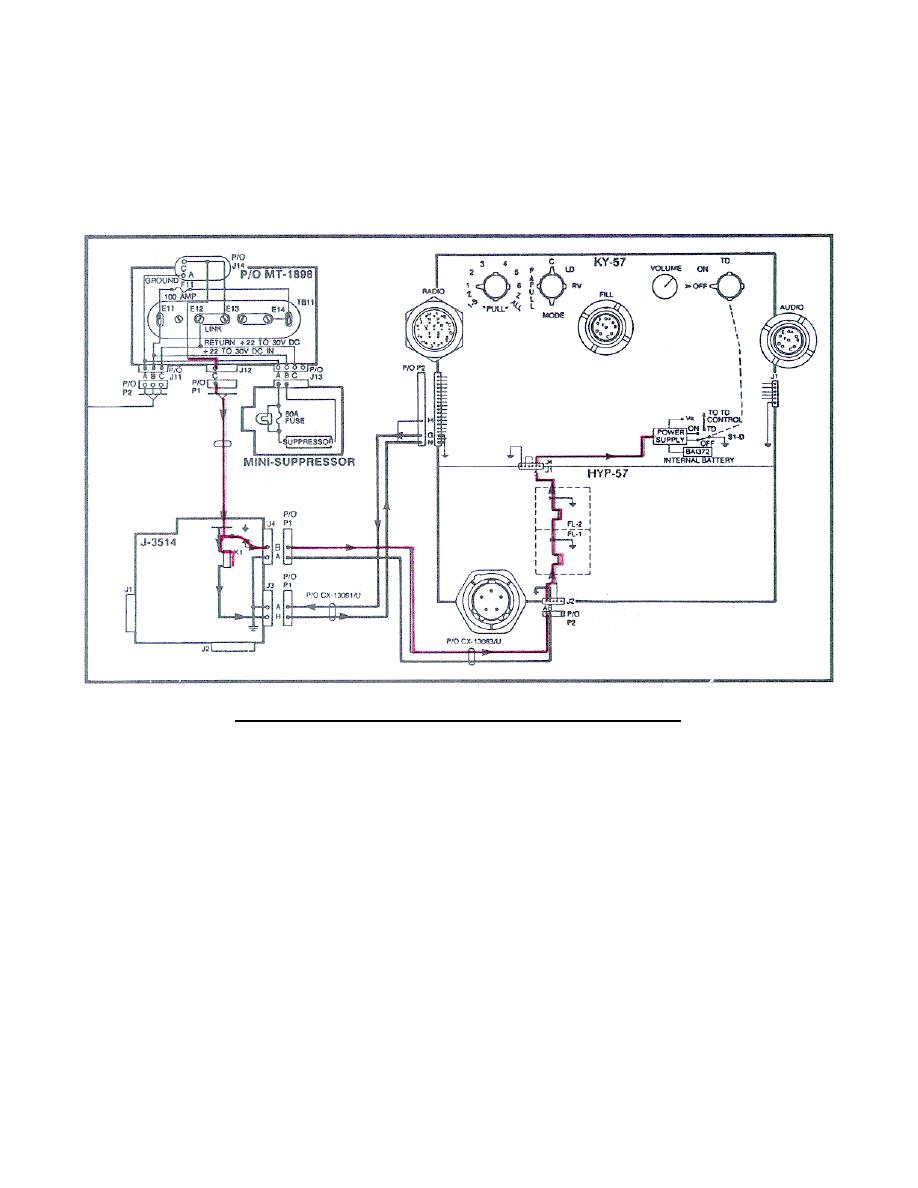
(4) Return power at the MT-1898 J12 pin C is applied to the J-3514
(through the K1 relay coil) to J3 pin H (through the CX-13061 pin N) to
ground. An additional ground returns from pin G (through the CX-13061/U) to
J3 pin A. With this ground complete, K1 relay coil energizes and K1 contact
closes. This applies voltage to J4 pin B (through the CX-13063) to the HYP-
57 and to the KY-57 power supply (Figure 45). (Trace these circuits on your
system diagram.)
Figure 45.
Return power to J-3514 and KY-57.
48


 Previous Page
