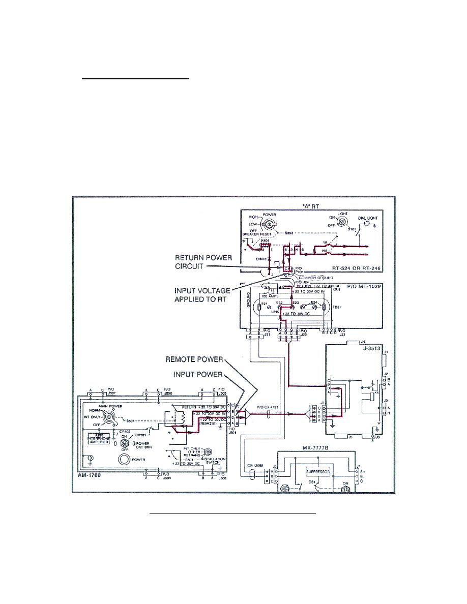
12. REMOTE AND RETURN CIRCUIT.
Refer to Block E of the Op Check (Appendix
A).
a. Remote power circuit. The remote power circuit begins when the AM-
1780 MAIN POWER switch is turned from INT ONLY to NORM (Figure 41). Input
power entering the AM-1780 at J501 pin B is applied through the lower
segment of S504 to pin D of J501; through the CX-4723, J-3513, and MT-1029
pin D. Voltage entering the MT-1029 at J22 pin D is applied to J24 pin J3,
through the link, to P401 pin J of the RT.
When the RT power switch is
turned to low, a ground is applied to K404 energizing the relay.
contact 6 mates with contact 4.
Input voltage from pin B of the RT is
applied to the 1 amp and 15 amp circuit breakers, providing the RT operating
voltage. Also, K404 contact 3 mates with contact 5 and the input voltage
from pin B is applied to P401 pin C, which begins the return power circuit.
(Trace these circuits on your system diagram.)
Figure 41.
Remote power circuit.
44


 Previous Page
