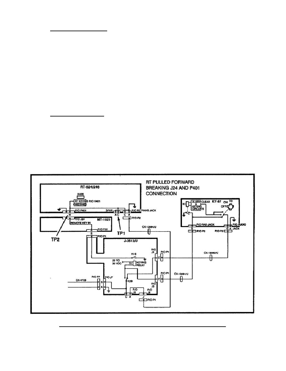
f. Test procedure 51. When you measured infinite ohms between pins C
and A on J5, that indicated the upper portion of the system keying circuit
is defective. (Test procedure 47.)
To find the bad item, loosen the mount wing nuts and pull the RT
forward.
This breaks the connection between J24 and plug P401 (Figure 81).
Now, measure continuity between pins A and C of the RT SPKR jack
(TP-1).
If the meter indicates zero ohms, the RT is bad.
g. Test procedure 52. If the meter indicated infinite ohms, when the
RT was pulled forward in the MT-1029. Disassembled the MT-1029 so the J-
3513 P1 can be removed from J22.
Measured Continuity between pins A and H J24 (TP2).
If the meter indicates zero ohms, the MT-1029 is bad.
If the meter indicates infinite ohms, the J-3513/U is bad.
Figure 81.
RT keying, continuous keying (upper loop).
94


 Previous Page
