Place AC/DC button in proper position (IN for audible tone).
2K range button IN and PEAK HOLD button OUT.
CAUTION
ALL SYSTEM POWER SWITCHES AND VEHICLE MASTER POWER SWITCHES ARE OFF.
d. Test procedure 1.
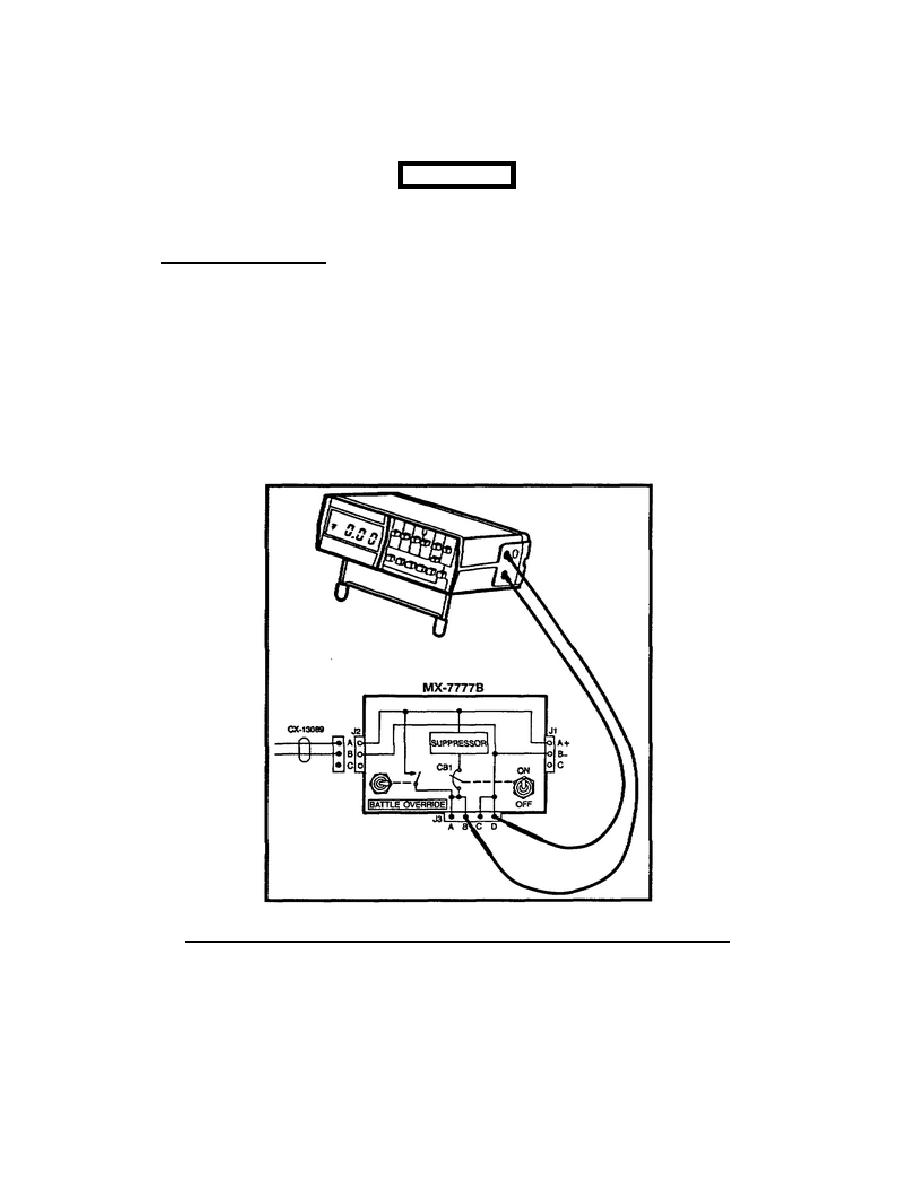
To connect the AN/PSM-45 to the system, remove
the CX-10613 from J3 on the MX-7777B.
Place a meter test lead in pin A or B of the MX-7777B J3, then
place the other meter test lead in pin C or D (Figure 20).
Set the MX-7777B power switch to ON, read the meter display, and
listen for an audible tone from the test set. If the meter shows
.000, the arrow on the left side of the display points down ,
and/or an audible tone is heard from the test set; one of the
possible bad items contains a short circuit.
Figure 20.
Multimeter AN/PSM-45 connected to MX-7777B.
21


 Previous Page
