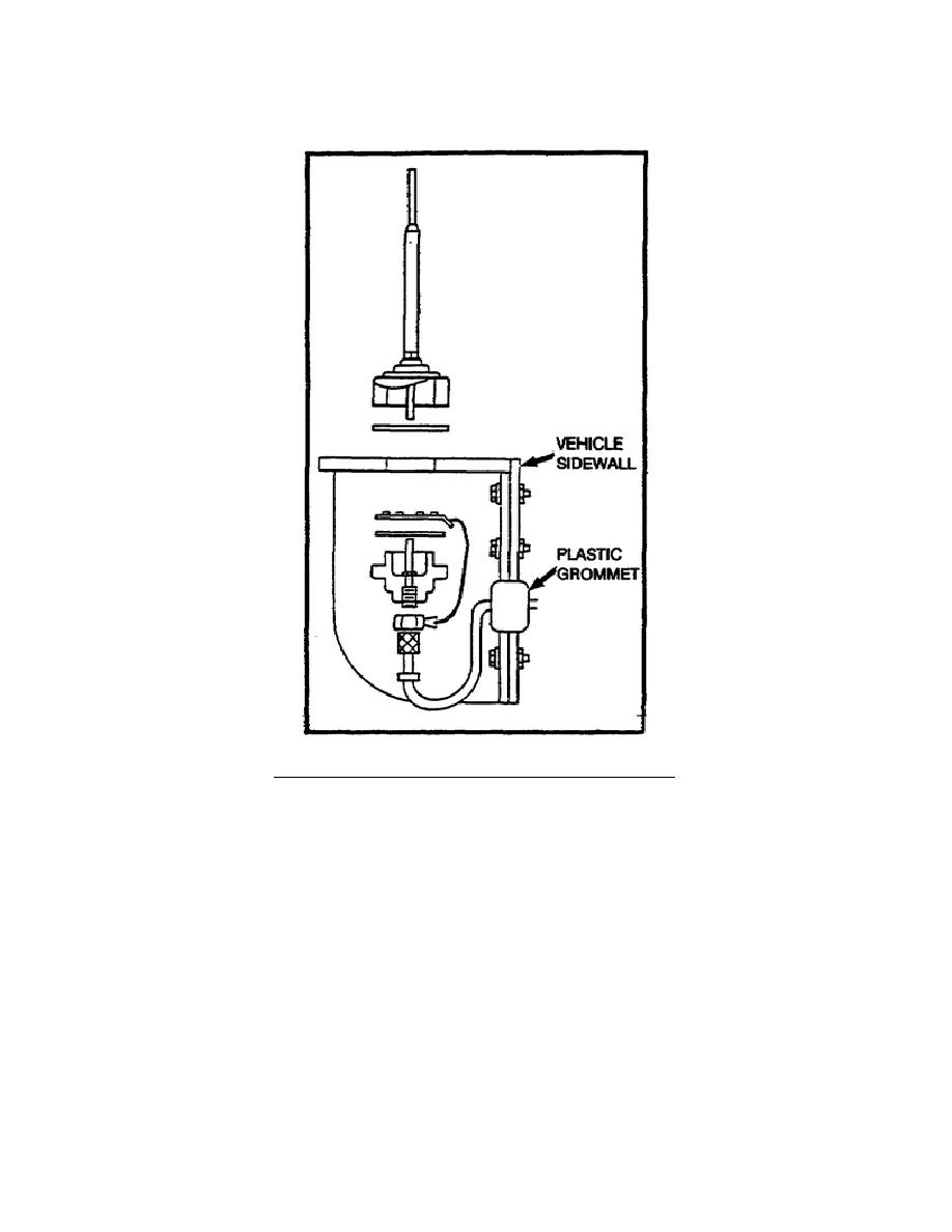
f. For all installations (except the vehicle top), insert the plastic
grommet in the hole in the vehicle sidewall (see Figure 7).
Figure 7.
Mounting antenna on bracket.
g. Perform steps 1 through 8 for system cabling (see Figure 8).
STEP 1.
Route the free end of the antenna cable through the hole(s)
(for side-mounted antennas), and connect it to the lower
connector J202 (A) on the back of the switching unit.
STEP 2.
Connect the battery power cable to the vehicle 24-volt DC
power receptacle (for vehicles with 24-volt DC power
receptacle). Use the connector plug and connector adapter,
as required.
STEP 3.
For vehicles without 24-volt DC power receptacles, attach
one terminal lug to the connected ends of the red and white
wires and one terminal lug to the connected ends of the
black and green wires of the power cable CX 4720.
8


 Previous Page
